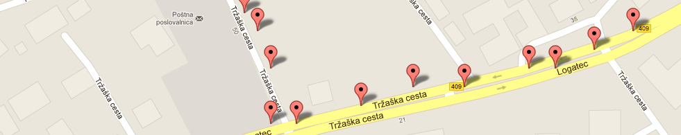
LOG-a-TEC
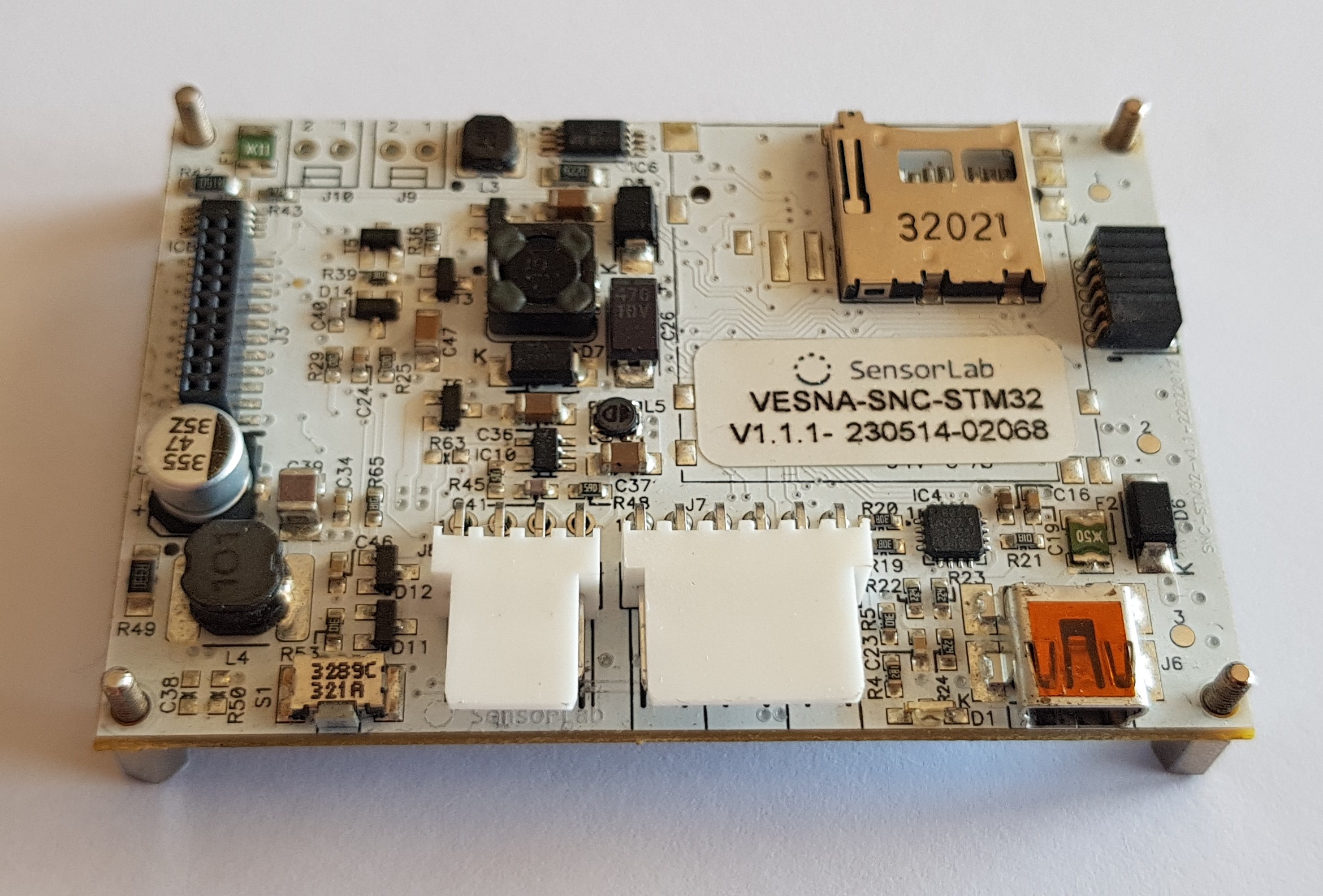
VESNA
VESNA is a modular and fully flexible platform for the development of wireless sensor networks developed at the SensorLab @ Jozef Stefan Institute. Based on the high-performance microcontroller with ARM Cortex-M3 core and radio interface spanning over multiple ISM frequency bands it is designed to meet the requirements of diverse applications.
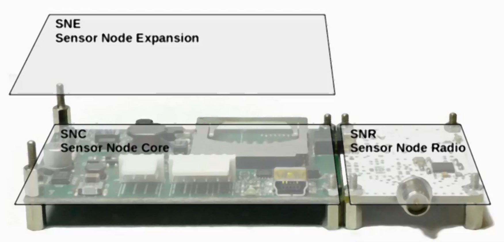
In terms of modularity the platform consists of the VESNA core module (SNC) and a set of special feature modules (sensor node radio – SNR, sensor node expansion – SNE, sensor node power – SNP) that are used as/if needed.
VESNA contains 512 kB FlashROM, 64 kB RAM and up to 2 GB SD card support for code and data storage. It can be powered with a variety of energy supply options including battery, solar panel and external power supply. Various peripherals including UART, I2C, SPI, USB, ADC and DAC allow hosting of different sets of sensors and/or actuators, for instance sensors for temperature, humidity, luminance, color, reflectance, pressure, presence, location, sound, acceleration, gasses, motion, range, and actuators such as motor, relay, servo, alarm, etc.
The platform readily supports:
- communication standards IEEE 802.15.4, IEEE 802.15.1 and IEEE 802.11;
- ZigBee, LoRa, 6LoWPAN, Bluetooth and Wireless M-Bus protocol stacks and technologies;
- connection to the Internet via Wi-Fi, Ethernet or GSM/GPRS;
- Arduino integrated development environment.
Depending on the application requirements, it can be operated with fully custom firmware or with frameworks and APIs provided by the Contiki-NG operating system.
Some additional information on VESNA platform can be found on our colleague's blog.
SNE-ISMTV radios
For the purpose of spectrum sensing in ISM and TV bands VESNA platform has been complemented by a SNE-ISMTV sensor node extension (SNE) board. SNE-ISMTV adds general-purpose radio-frequency transceiver hardware to the VESNA wireless sensor node. This hardware is separate from the SNR (sensor node radio) transceiver used to connect VESNA nodes into a wireless management network. SNE-ISMTV can thus be used for cognitive radio experimentation without disrupting the back-channel network as long as any experimental transmissions are not overlapping with the frequency bands used by the SNR. SNE-ISMTV applications include for example spectrum sensing, continuous and packet-based signal transmission and reception with RSSI and link quality measurements, and IEEE 802.15.4 compatible networking experiments. Several models of the extension board are available covering different parts of the spectrum. Their capabilities differ slightly and are described in detail in the following subsections.
SNE-ISMTV radio hardware is based on commercial, low-cost, low-power, highly integrated transceivers that communicate with the core board using digital SPI or I2C buses. In all but one case (SNE-ISMTV-UHF low-range detection) all radio-frequency and base-band processing is done in the transceiver, freeing the VESNA SNC (sensor node core) microcontroller from signal processing tasks. In most cases, communication with the radio is abstracted in the form of various hardware registers with read and/or write access via digital buses. These registers can be used to reconfigure radio hardware (central frequency, channel filter bandwidth, modulation and demodulation settings, signal generation, etc.), send data for transmission or retrieve received data, retrieve measurement results and so on. While SNE-ISMTV does not include a true general-purpose software-defined radio architecture, the reconfigurability of the radio components still allows for a large range of use cases.
Manufacturers of the integrated circuits used in SNE-ISMTV do not support all of the possible transceiver hardware configurations that can be obtained through register access. In fact, due to implementation details radios may not perform to specification in certain combinations of settings. This means that each configuration usually requires testing and calibration in a controlled laboratory environment before it can be used for experiments in the field. To work around this shortcoming several tested and calibrated hardware profiles are provided for each SNE-ISMTV model that cover specific use cases and contain a fixed low-level radio configuration.
All models of the SNE-ISMTV carry two distinct transceivers:
- An IEEE 802.15.4 compatible transceiver. Either based on Atmel AT86RF212 operating on the European 868 MHz SRD (short range device) frequency band or based on Atmel AT86RF231 operating on the international 2.4 GHz ISM (industrial scientific medical) frequency band.
- another multipurpose radio operating in either UHF TV band, 868 MHz SRD band or 2.4 GHz ISM band.
TV band spectrum sensing with SNE-ISMTV-UHF
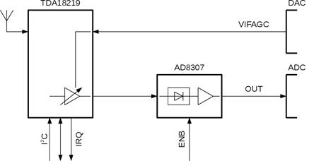
SNE-ISMTV-UHF contains a VHF and UHF TV band receiver based on the NXP TDA18219HN silicon tuner and was designed for spectrum sensing experimentation in TV white spaces. The TDA18219HN silicon tuner integrates a low-noise amplifier, RF tracking filters, single down-conversion low intermediate-frequency image-rejection mixer, frequency synthesizer and selectable channel filters. It also includes multiple stages of analogue automatic gain control (AGC).
Individual receiver stages can be reconfigured through a state machine with an I2C bus interface. Digital control logic also controls built-in test tone generator and RF filter calibration.
For energy detection SNE-ISMTV-UHF offers two detectors with a logarithmic response. A high-range detector is built into TDA18219HN and has a range from -80 to 0 dBm with 1 dBm resolution. The measurement is controlled via a state machine internal to TDA18219HN which is armed and triggered through the digital I2C bus. The measurement process includes signal averaging.
For measuring signals below -80 dBm, a demodulating logarithmic amplifier Analog Devices AD8307 is connected between the TDA18219HN intermediate frequency output and the 147 ksample/s analogue-to-digital converter on the VESNA SNC (sensor node core) as depicted in the figure below. This puts sampling of the signal power level in control of the firmware, allowing various averaging and sampling methods. Additionally, gain in the intermediate frequency stage can be adjusted via a variable-gain amplifier controlled by a digital-to-analogue converter (DAC) in the SNC.
To lower the power consumption, both the logarithmic amplifier (via ENB pin) and the tuner (via I2C sleep-mode control registers) can be powered down.
Two hardware profiles are provided that differ in energy detector resolution bandwidth. A wide-band setting sets the channel filter to 8 MHz, allowing energy detection at the bandwidth of a complete DVB-T channel. A narrow-band setting sets the channel filter to 1.7 MHz and is suitable for detection of wireless microphones and secondary users in the TV white spaces.
While TDA18219HN and the SNE-ISMTV designs allow operation down to 42 MHz, there are currently no hardware profiles available for VHF frequency band.
Since it is based on a DVB-T tuner, this extension board is not capable of signal transmission in contrast to the extension boards SNE-ISMTV-TI868 and SNE-ISMTV-TI2400, as described in the following subsections.
The SNE-ISMTV-UHF spectrum sensing specifications are summarized in the table below.
| Parameter | Value | Units | Comment |
| Frequency range | 470 to 862 | MHz | |
| Frequency resolution | 1 | kHz | |
| Local oscillator settle time | 5000 | us | |
| Channel filter bandwidth | 1700 8000 |
kHz | |
| Power detector range | -150 to 0 | dBm | |
| Power detector resolution | 1.000 0.032 |
dB | above -80 dBm below -80 dBm |
| Power detector uncertainty | 1.76 | dBm | CW at -90 dBm, no averaging |
| Detector read-out time | 45000 1 |
us | above -80 dBm below -80 dBm |
| Average noise level (1 Hz bandwidth) | -169 -165 |
dBm | at 650 MHz at 800 MHz |
| Dynamic range | 60 | dB | With total input power over the entire frequency range below -30 dBm. |
SNE-ISMTV-UHF specifications
868 MHz ISM Sensing and transmission with SNE-ISMTV-TI868
SNE-ISMTV-TI868 contains a sub-GHz transceiver based on the Texas Instruments CC1101. CC1101 contains a versatile radio-frequency tuner as well as a modem and packet handling hardware. It can be used for experiments in the European 868 MHz SRD band or in the higher channels of the UHF TV band. It can act as a narrow-band energy detection spectrum sensing receiver, interferer with continuous test signal transmission or for packet transmission and reception in networking experiments.
The analogue receive path on CC1101 consists of a low-noise amplifier, quadrature down-converter and a channel filter. Additional filtering, gain control and demodulation are performed in the digital domain, after the signal has been digitized by an analogue-to-digital converter (ADC) at an intermediate frequency. A fractional-N PLL frequency synthesizer is used as a local oscillator. For transmission, the same synthesizer is used to produce a modulated quadrature signal which is amplified by a power amplifier stage. Antenna matching is performed by an external LC balun network.
Digital radio control logic allows reconfiguration of the frequency synthesizer settings (base frequency, channel spacing) and baseband channel filter bandwidth.
Baseband modulator and demodulator are capable of 2-FSK, 4-FSK, GFSK, MSK and ASK/OOK modulations. Continuous transmission and reception using these modulations is possible with data streamed via the SPI bus from the sensor node core (SNC) module. Additionally, a pseudo-random sequence generated in the transceiver itself can be used when transmitting in continuous mode, which can be used in interferer simulations.
For packet-based transmissions, integrated packet handling hardware implements a proprietary packet encapsulation scheme. It includes preamble and synchronization word detection, data integrity check using CRC, address filter and optional data whitening.
For energy detection, an integrated logarithmic-response detector can be used. Three hardware profiles are provided for it, covering the 868 MHz SRD band with different resolution bandwidths.
The spectrum sensing specifications of the module are summarized in the first table below, while the signal transmission specifications are provided in the second table. For signal transmission experiments, a hardware profile is provided simulating a 200 kHz wide-band FM wireless microphone in the UHF band with adjustable transmission power. Additionally, a profile of a short-range device is also available with transmission in the SRD band using 100% duty cycle.
Additional sensing or transmission profiles can be constructed using the SmartRF studio software provided by Texas Instruments.
| Parameter | Value | Units | Comment |
|---|---|---|---|
| Frequency range | 863 to 871 | MHz | |
| Frequency resolution | 50 | kHz | |
| Channel filter bandwidth | 60 100 200 | kHz | |
| Power detector range | -123 to 4 | dBm | |
| Power detector resolution | 0.5 | dB | |
| Average noise level (1 Hz bandwidth) | -150 | dBm | at 868 MHz |
SNE-ISMTV-TI868 receiver specifications
| Parameter | Value | Units | Comment |
|---|---|---|---|
| Frequency range | 780 to 862 863 to 871 |
MHz | |
| Frequency resolution | 200, 50 | kHz | |
| FM deviation | 200, 50 | kHz | |
| Transmission power range | -55 to 0 | dBm | |
| Transmission power resolution | 2 | dBm |
SNE-ISMTV-TI868 transmitter specifications
2.4 GHz ISM Sensing and transmission with SNE-ISMTV-TI24
SNE-ISMTV-TI24 contains a 2.4 GHz transceiver based on the Texas Instruments CC2500. CC2500 contains a versatile radio-frequency tuner as well as a modem and packet handling hardware. It can be used for experiments in the international 2.4 GHz industrial, scientific, medical (ISM) band. It can act as a narrow-band energy detection spectrum sensing receiver, interferer with continuous test signal transmission or for packet transmission and reception in networking experiments.
Performance and capabilities of SNE-ISMTV-TI24 are very similar to SNE-ISMTV-TI868 since, as shown in Figure 12, CC2500 integrated circuit is very similar to CC1101. Both extension boards share the same pin-out as well as SPI register map, the only difference being in the settings for the analogue domain. Therefore the description of the SNE-ISMTV-TI868 given in Section 3.1.2also applies to SNE-ISMTV-TI24.
The spectrum sensing and signal transmission specifications are provided in the first table and the second table below. For energy detection spectrum sensing, a hardware profile is provided covering the frequencies used by IEEE 802.11b wireless LAN.
For interferer simulation, a hardware profile is provided for a continuous transmission of a 200 kHz FM signal with adjustable transmission power.
Additional sensing or transmission profiles can be constructed using the SmartRF studio software provided by Texas Instruments.
| Parameter | Value | Units | Comment |
|---|---|---|---|
| Frequency range | 2400 to 2480 | MHz | |
| Frequency resolution | 400 | kHz | |
| Channel filter bandwidth | 400 | kHz | |
| Power detector range | -123 to 4 | dBm | |
| Power detector resolution | 0.5 | dB | |
| Average noise level (1 Hz bandwidth) | -159 | dBm | at 2400 MHz |
SNE-ISMTV-TI2400 receiver specifications
| Parameter | Value | Units | Comment |
|---|---|---|---|
| Frequency range | 2400 to 2459 | MHz | |
| Frequency resolution | 200 | kHz | |
| FM deviation | 200 | kHz | |
| Transmission power range | -55 to 0 | dBm | |
| Transmission power resolution | 2 | dBm |
SNE-ISMTV-TI2400 transmitter specifications
SNE-ESHTER radio
SNE-ESHTER is an evolution of the SNE-ISMTV-UHF spectrum sensing receiver, which was successfully used in a number of experiments involving detection of wireless microphones and DVB-T transmissions.
The original design proved to be reasonably robust. During the operation of the testbed none of the 8 SNE-ISMTV-UHF devices deployed in an out-door environment failed. Also, the small size of the receiver proved to be convenient when performing mobile measurements. The absolute power measurements it provided were reasonably accurate and the internal receiver noise floor proved to be excellent.
However the fact that its hardware design only allowed for energy detection meant that SNE-ISMTV-UHF was not capable of supporting state of the art experiments with advanced spectrum sensing methods. Even with energy detection the receiver had a disadvantage of a relatively high minimum channel bandwidth of 1.7 MHz compared to the typical 200 kHz bandwidth of PMSE transmissions in the TVWS.
Because of this we decided to design an updated version of the receiver. With the update we intend to address some of the most common comments from internal and external experimenters using our testbeds in the TV whitespaces. We call the new design SNE-ESHTER, short for “embedded sensing hardware for TVWS experimental radio”.
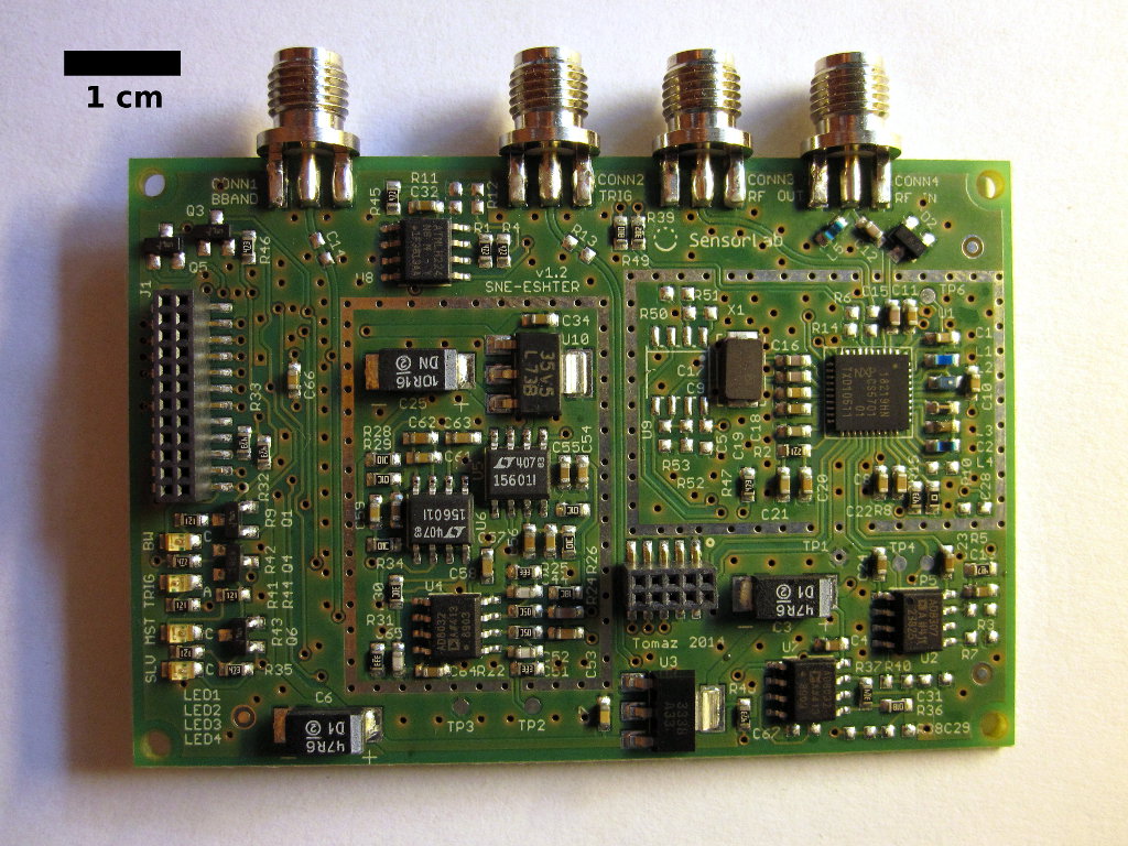
SNE-ESHTER circuit board.
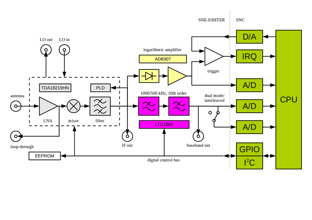
SNE-ESHTER block diagram.
Possibility of capturing signal traces
In SNE-ISMTV-UHF the baseband signal from the tuner was routed through an analog detector and logarithmic amplifier and then sampled at a low sampling rate (147 kHz) with an 12-bit analog-to-digital converter (ADC) integrated into the sensor node core's CPU.
This design made it possible to measure baseband signal amplitude with an excellent dynamic range and sensitivity beyond what would be possible with a 12-bit ADC. It also made it possible to measure the signal amplitude without excessively loading the relatively low-powered sensor node core CPU as only around a 100 ADC samples of the analog detector output were typically needed to calculate the amplitude to the desired accuracy. On the other hand the use of the ADC already present on the sensor node core made it possible to keep a small physical size and low component count. It also removed the need for high-speed digital busses on the receiver board, which helped reduce the electro-magnetic interference (EMI) from the digital part of the circuit.
The inclusion of a non-linear component (the analog detector) in the signal path however meant that it was not possible to recover the original signal waveform on the CPU side. Even if the sampling rate of the ADC would be increased, only the square function of the signal (x[n]2) could be approximated. Spectrum sensing methods other than energy detection however require access to the unmodified signal samples (x[n]) and were hence not possible to implement with this hardware.
To address this shortcoming, we added an additional signal path to the receiver that skips the detector and logarithmic amplifier and routes the baseband signal from the tuner to two ADC converters on the core board. The sampling rate on the core board has been increased to 1 MHz. This allows the capture of signal at 1 Msample/s when using a single ADC and 2 Msample/s when using two ADC in a fast dual-interleaved mode. It should be noted however that while the receiver hardware and the ADC are capable of sustaining a 2 Msample/s stream, the CPU is not capable of processing it in real-time. Therefore we predict that the typical use case for this mode of operation will be to a capture a buffer of signal samples, followed by offline signal processing. The amount of RAM on the CPU allows for a single of capture length of up to 25 ksamples (12.5 ms with 2Msample/s).
To make it possible to directly sample the baseband signal with ADC converters on the core board, additional analog signal conditioning components were required. Channel filters integrated into the TDA18219HN tuner can only limit the baseband bandwidth down to 1.7 MHz. To prevent aliasing with 1 and 2 Msample/s ADC, an additional analog, 10th order elliptic low-pass filter was inserted between the tuner and the ADC. The filter bandwidth can be set from software to 1 MHz or 500 kHz, allowing for optimal signal bandwidth in both 1 Msample/s and 2 Msample/s modes. Addition of the analog filter required a balanced-to-unbalanced signal conversion and an additional on-board low-noise 10V power supply. These additions were responsible for most of the increase in circuit component count compared to the old design.
In addition to enabling experimentation with advanced spectrum sensing methods, the new direct signal path in SNE-ESHTER can also be used for energy detection with a lower resolution bandwidth than what was possible with SNE-ISMTV-UHF. The additional filter lowers the channel bandwidth to 1 MHz or 500 kHz. By calculating the signal energy in software from an appropriate array of baseband samples it is possible to also perform energy detection at 1 MHz and 500 kHz bandwidths. This way SNE-ESHTER allows recording swept-tuned spectrograms with a higher frequency resolution than those possible with SNE-ISMTV-UHF. Hence this change addressed another common request from experimenters using SNE-ISMTV-UHF. It should be noted though that with the absence of a logarithmic amplifier, the dynamic range of this mode of energy detection is limited by the 12-bit ADC.
Possibility of two coherent signal chains
Some spectrum sensing methods require signal capture from two antennas, possibly with coherent sampling. To make this possible with SNE-ESHTER, two features were added to the new design: dual-receiver operation and external clock reference.
The assignment of pins on the standard stackable VESNA expansion connector was changed in a way that allows for two SNE-ESHTER boards to be stacked on top of each other, as shown on Figure . In such a configuration, we refer to the top board as “slave” and the bottom board as “master” board. Routing of pins between the top and bottom expansion connectors on SNE-ESHTER allows for a single circuit board design to act as both a master and a slave board, eliminating the need for two separate designs for the two roles.
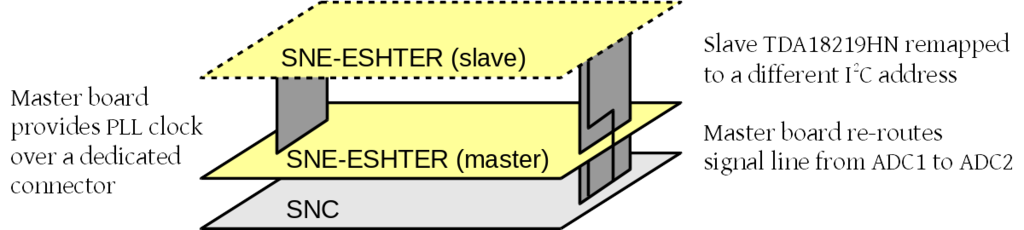
Stacking two SNE-ESHTER boards
In dual-receiver operation, both SNE-ESHTER boards share the same control signals and behave identically. The only difference is that addresses on the I2C are remapped on the slave board. This allows software to control both tuners independently. For example, boards can be set to the same central frequency to sense the same channels using two antennas or, by using the loop-through functionality on the master board, two channels from the same antenna.
The baseband from the slave board is routed to the secondary ADC on the sensor node, while the primary ADC samples the baseband from the master board. In this case the two converters operate in the dual-simultaneous mode, coherently sampling both signals. Only 1 Msample/s sample rate is supported in the dual-receiver configuration.
The UHF tuner on SNE-ISMTV-UHF used an on-board 16 MHz crystal oscillator as a reference clock from which it derived the LO frequency using an integrated PLL. In SNE-ESHTER we retained this functionality and also added the possibility of running the tuner from an external reference clock instead of the on-board oscillator. To achieve this, the SNE-ESHTER board can be fitted with a clock input connector on the bottom of the board and appropriate clock buffers. In this case the crystal oscillator on the board is not used and the LO frequency is derived from the external clock signal.
In dual-receiver operation, a slave board with the clock input connector can be used. In that case the clock output connector on the top of the master board and clock input connector on the slave board connect. Tuners on both boards hence run synchronously from the same oscillator. This eliminates unpredictable phase shifts between the two baseband signals that would be caused by two free-running local oscillators.
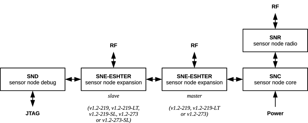
Block diagram of a VESNA sensor node with all possible expansion boards.
Enable faster responses to signal power changes
One of the comments regarding SNE-ISMTV-UHF was that in order for the CPU to respond to a change in the signal level, it must continuously perform analog-to-digital conversions. ADC sampling is relatively slow compared to the core CPU clock. In some use cases timing is critical, for example in carrier-sense media access protocols (CS-MAC). For those cases it would be preferable if the radio frontend could independently raise an interrupt request on the sensor node code CPU when a channel becomes vacant.
To address these comments a trigger subsystem was added to SNE-ESHTER. SNE-ESHTER retains the signal path through the analog detector and logarithmic amplifier that was present in SNE-ISMTV-UHF. A comparator circuit was added to that signal path that compares the signal level to a threshold value set by the CPU. When the detected signal level in the tuned channel passes the threshold, an interrupt request is sent to the CPU. The interrupt can be triggered on both the falling edge (i.e. a channel has become vacant) and rising edge (a channel has become occupied). In the latter case, SNE-ESHTER can be switched to signal sampling mode with minimal latency, which allows for accurate triggering of signal sample collection when a sufficient signal level is detected. This capability can be useful for example to trigger advanced signal analysis only when energy detector detected significant power present in the channel.
On-board storage of serial number and calibration tables
SNE-ISMTV contained no on-board non-volatile memory. It required that the firmware running on the sensor node core was manually programmed with correct calibration tables for the physical receiver that was installed on it. Because of this, only one average calibration table was used typically used in practice for all deployed nodes to remove the need for customized firmware images for each individual sensor node. This reduced the accuracy of measurements due to inaccurate calibration tables.
There was also no programmatic way for the software to read the serial number of the hardware. This proved problematic when tracking deployment of a large number of sensor nodes in LOG-a-TEC testbeds. Reproducibility of experiments also depended on the experimenter manually noting the serial numbers of hardware involved in the experiment.
To address these comments, we added a small amount of non-volatile EEPROM memory to SNE-ESHTER. Typically we predict that a calibration table will be written to the EEPROM once after the board has been tested. Firmware on sensor node core could then download the table from the board as needed. The specific EEPROM integrated circuit we used also provides a factory-programmed, read-only 128-bit identifier that can be used by the sensor node firmware to uniquely identify the radio that is installed.